A Look at the Rigidity of Benchrest Barrels
January 18, 2015 8:47 pmWhile there are a number of factors that determine the accuracy of a rifle barrel, one of the more critical elements is its stiffness or rigidity. Obviously the larger in diameter a barrel is, the stiffer it will be. Almost as obviously, as the length of a barrel increases it becomes more limber. So, there is a trade off of sorts if our goal is a stiff barrel, and as a result a potentially more accurate one. If we are limited to a barrel of a certain weight, as we are with a varmint or hunter class rifle, the compromise becomes length verses diameter.
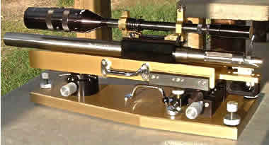
in a barrel-block. This is a super-stiff barrel.
When a cartridge is fired in a chamber, the barrel undergoes many stresses. It begins to vibrate when the firing pin starts its fall and these vibrations increase dramatically from then on. During recoil and while the bullet is still in the barrel, the barrel will whip vertically. This happens because the thrust axis of the rifle is above the centerline of the stock. During recoil the barrel comes back and up. The muzzle will lag behind the rest of the barrel in this movement and the vertical whipping motion is set up. While these vibrations of the barrel are very small, they do exist. The stiffer a barrel is, the less the muzzle will jump around. This brief description is of course an oversimplification of the dynamics that take place, but they do point out the type of barrel movements occurring and why a stiffer barrel is more accurate.
The stiffness of a barrel can be determined mathematically by knowing a little about the physics involved. A free-floating rifle barrel is a classic example of a cantilevered beam supported at one end and with a load applied to the other, the muzzle end. The basic formula for calculation of muzzle deflection is:
D = (W*l^3)/3*E*Ix
where D is the deflection at the muzzle in inches, W is the force or load applied at the muzzle in pounds, l is the free length of the barrel in inches (not including threads), E is the modulus of elasticity or Young’s modulus for the barrel material, and Ix is the moment of inertia for the barrel.
While it is difficult if not impossible to determine the exact force on the muzzle, we can compare the stiffness of one barrel to another by plugging the same load (W) into the formula. In all of the examples shown, this force will be one pound.
The length of a barrel is easily measured. Perhaps surprisingly though, we can see from the formula that the cube of the length is used. This indicates that rigidity decreases greatly as barrel length increases.
The modulus of elasticity is a constant, and in the case of steel it is 30 million PSI. Regardless of the heat treatment of the steel or its alloy, this modulus does not change. So unless we are dealing with a barrel made from some other material, this part of the equation remains the same.
Most gunsmiths are familiar with a somewhat similar example to our rifle barrel, modeled after a beam supported at one end: the boring bar used on a lathe. The farther out the boring bar is slid from its holder, the more easily it deflects during a cut. Increasing its diameter would help greatly, but the diameter of the hole being bored limits bar size. For this reason, the best quality boring bars available are made from solid carbide – that is, the bar itself is carbide. The modulus of elasticity for carbide is about 94 million PSI, or over three times that of steel. As a result, the carbide bars are more than 3 times as still.
With rifle barrels we are limited to steel, but this example shows the importance that the modulus of elasticity plays in overall stiffness.
The moment of inertia of a barrel is the most difficult part to calculate. It is a measure of the cross sectional area of the barrel. A larger diameter barrel will have a higher moment of inertia value and as a result will be stiffer. Calculating the moment for a straight cylinder barrel is relatively easy though. The equation looks like:
Ix = Pi *(D1^4 – D2^4)/64
where; again, Ix is the moment of inertia; Pi is 3.1416; D1 is the outside diameter of the barrel and D2 is the barrel groove diameter. From this equation we can see that the moment of inertia increases with the fourth power of the diameter. As an example of this significance it might be interesting to note that a 2″ diameter barrel is 16 times stiffer than a 1″ diameter barrel because 2^4 is 16.
Figuring the moment of inertia for a straight tapered barrel, such as a heavy varmint barrel, is much more difficult requiring an integration over its entire length. While I was shooting at the 1991 NBRSA Nationals in Midland, Texas, I had the good fortune of sitting next to my friend Mel Klasi of Rapid City, South Dakota. For those who don’t know Mel, he is a professor of Civil Engineering at the South Dakota School of Mines and Technology. Sometime during the week I mentioned to Mel that I was working on a computer program to calculate barrel stiffness. At that time I had the program working for unlimited type barrels but told Mel that I was not getting anywhere fast on the integration aspect for tapered barrels. Mel volunteered to derive the equations for me and a few weeks after getting home I got a nice little floppy disk in the mail that did the calculations. I’m very grateful to Mel for his efforts in this. Without his input, I probably wouldn’t be writing this article. Mel’s equations are too lengthy and involved to show them here though.
When dealing with a weight limit for a rifle barrel, as we usually are, what we want then is the highest moment of inertia for the barrel. As we pointed out, increasing the diameter is the way to achieve this. We are limited by NBRSA rules however to a maximum set of barrel dimensions. This maximum barrel is one that is 1.250″ in diameter for a length not greater than 5″ at the chamber end with a straight taper to a diameter of .900″ at a length of 29″. This is a taper of .01458″ per inch. A heavy varmint class rifle can easily make weight utilizing this maximum barrel configuration. The amount of weight left from 13.5 pounds for the barrel usually determines the barrel length. Often it is from 22-25 inches long.
When dealing with a light varmint rifle however, limited to 10.5 pounds total weight, usually about half of the weight is in the barrel or about 5 pounds 4 ounces. To utilize a maximum heavy varmint contour barrel and have it weigh 5 and a quarter pounds means the barrel can be no longer than about 18.60″. This is shorter than most will accept. The trend today is, from my observation, for a light varmint barrel of around 22″. Some like them even longer, up to 24″ or so. To get these longer barrels we have several choices; 1) we can cut off some of the chamber end of a heavy varmint barrel and use more of the skinny end; 2) we can use a smaller diameter barrel blank, perhaps having more taper per inch, or; 3) the barrel can be fluted.
If the barrel is fluted a maximum heavy varmint blank is usually used and for good reason. As we saw above, the larger the diameter, the stiffer it is going to be. Using a heavy varmint blank then gives us the maximum diameter allowed. Fluting a barrel removes weight, up to one pound or so depending on flute size. It also lowers a barrel’s moment of inertia value but not by very much. Some have the mistaken idea that fluting alone increases the stiffness of a barrel. This is not true. The fluted barrel of a given weight and length will be stiffer than an unfluted barrel of the same weight. The fluted barrel will not be stiffer than the same taper and length barrel that is not fluted though.
If either of the first two options for selecting a 5 pound 4 ounce barrel mentioned above were used, I wondered what barrel contour would be the stiffest. To find out I incorporated the rigidity calculations mentioned already with the barrel weight calculations that I wrote about in the February 1990 issue of NBRSA NEWS. I was then able to easily calculate with the computer, the weights, lengths, diameters, and muzzle deflection for a variety of straight taper barrel configurations all weighing 5 pounds – 4 ounces. The results of this can be seen in the accompanying table. Without the aid of a computer, these calculations would have been so time consuming and lengthy that they never would have been done, at least not by me.
I also made some calculations for maximum heavy varmint dimension barrels of varying lengths. I did the same for different diameter straight cylinder, unlimited type barrels, all of the same length. The results were revealing.
For example, I found that a 24″ heavy varmint barrel is 32% stiffer than a 26″ version. A 22″ HV barrel is about 35% stiffer than that 24″ barrel and an 18″ HV barrel is 98% stiffer than the 22″ barrel. Remember the earlier statement about length being raised to the third power in the deflection equation? The 18″ barrel is 3.51 times stiffer than the 26″ barrel. Interesting?
I left the lengths of the unlimited barrels the same, 24″ with a 1″ thread shank, leaving 23″ of free barrel. I found that the 1.350″ diameter barrel was 36% stiffer than the 1.250″ diameter barrel and that the 1.450″ diameter barrel was 33% stiffer than the 1.350″ example. Because I’ve made a few barrels from 1 7/8″ diameter material, I wondered about them, too. A 1.850″ diameter barrel is 2.65 times stiffer than the 1.450″ barrel and it is also 4.80 times more still than the 1.250″ barrel. Again this emphasizes the importance played by diameter and the resulting higher moment of inertia in rigidity. They play it to the tune of diameter raised to the fourth power.
When I calculated the deflection for the barrels all weighing 5 pounds – 4 ounces, there were a few surprises. Remember now, these examples all weighed the same but contour and length changed. The stiffest barrel was the already mentioned 18.60″ long maximum heavy varmint barrel. The second stiffest barrel was one from what I call a 1.200″ heavy varmint blank. It is just like a maximum heavy varmint blank but its diameter is .050″ smaller its full length. This barrel is almost 21″ long and utilizes all 5″ of the 1.200″ diameter cylinder. It fared so well because of the full use of the cylinder before the taper. The next stiffest barrel was a maximum heavy varmint blank with four of its five inches of 1.250″ diameter cylinder cut off. With a 1″ long thread shank (as all the examples have), this left no cylinder in front of the receiver. This barrel was 20.92″ long to make the 5 and one quarter pound weight limit. At this length, almost 21″, it is long enough that most shooter would accept it. That is probably not true of the short 18.6″ long maximum heavy varmint barrel that was the stiffest. This barrel and the previous one are really of the same stiffness for all practical applications, just .000012″ of deflection difference between them. The next stiffest barrel surprised me. It was a maximum Hunter class diameter barrel using all four inches of allowable 1.250″ diameter shank. It came in at 21.85″ in length and has a taper of .02273″ per inch. The reason this barrel fared so well has to do with its maximum 1.250″ diameter shank at the receiver. Remember the importance of diameter in the moment of inertia calculation. Even over the entire barrel length integration, this maximum diameter, at the breech end, was important. In all honesty, I thought this Hunter barrel would do poorly and used it as an example just to see how badly it would do. Everyone knows how whippy looking those Hunter barrels are.
The worst barrel was the longest – almost 24″ long, with a straight taper from 1.200″ diameter at the receiver but with no cylinder section. For interest, I also calculated the maximum length 1.250″ straight cylinder barrel that would still make weight. It was about 16.5″ long and obviously the stiffest of the bunch. It is not legal for use in matches though for two reasons, one, it doesn’t meet the diameter requirements of the rulebook, and it is also shorter than the minimum 18″ required by the rules. This barrel is the first one listed on the chart under 5 pound – 4 ounce barrels.
Looking at the chart, we can see that as the length of the barrel increases, its stiffness decreases. The stiffest barrel is the shortest and the longest one is the most limber. With just a .050″ difference in cylinder diameters in these barrels, the full importance of barrel diameter is not realized as it is with the unlimited barrels.
Another question is, does the caliber of the barrel make any difference in stiffness? The answer: yes it does, but not a great deal. To find out I ran calculations for two 1.250″ diameter straight cylinder barrels both 23″ long. One of them was a .224 caliber and the other .308 caliber. As might be assumed the 22 was stiffer but not by that much. It would deflect .000112″ under the one pound load and the 30 would bend .000132″. This means the 22 is about 17% stiffer. In the moment of inertia formula, the caliber is raised to the fourth power and subtracted from the outside diameter raised to the fourth power. When dealing with decimals this results in a fairly small number in the equation from the inside hole diameter.
We can see from these examples that the short and fat barrel is the stiffest. To a degree, fatness is better than shortness (don’t forget we’re discussing barrels now). The reason goes back to the original equation where length is raised to the third power but diameter is raised to the fourth power in moment of inertia calculations. So, if you need more weight in a barrel and you’re wondering whether to make the barrel longer or larger in diameter, especially at the receiver end, I’d suggest going with the increased diameter.
This discussion about length brings me to another point. I think one of the reasons that barrel block unlimited-type rifles shoot so well has to do with the block. Depending on how the barrel is clamped, the free end of the barrel that is left to vibrate is that part of the barrel beyond the block. It is not quite that simple because everything in contact with the barrel is going to vibrate but the block will surely dampen most of the whipping from the clamped portion of the barrel back to the receiver. With a 24″ barrel and a 1″ thread shank and a 6″ block, that leaves about 17″ of barrel to vibrate. If we take as an example two 1.450″ diameter barrels, one blocked as just mentioned and the other free-floating in front of a conventionally bedded receiver, we are comparing a 17″ barrel and a 24″ barrel. The difference in rigidity may surprise you; it did me. The shorter barrel is 2.48 times stiffer.
With a long barrel on a long-range rifle or 1000 yard benchrest rifle, the barrel blocks become even more important. With a 30″ long barrel, not only is there much unsupported barrel able to vibrate, but that extra length adds up to quite a bit of weight. Hanging 15 pounds of barrel from a short receiver thread shank is a good way to stretch threads and mess up a conventional bedding job too. Perhaps more than any other rifle type, these rifles benefit from a barrel block.
It is probably for this same reason that the short barrels on the Remington XP-100’s shoot as well as they do. Phenomenally well in many cases. The little 14-15″ tubes are very rigid.
Another advantage to the short barrels is the relocation of the center of gravity towards the shooter. In my opinion a muzzle heavy rifle is hard to control on the sand bags and may cause some vertical stringing in a group. I like the balance point to be as far back as is reasonably possible.
We can see from these numbers that both length and diameter are very important in determining barrel stiffness and potential accuracy. If the advantages of a short and fat barrel are clear, an obvious question is, are there any disadvantages? The only real disadvantage to the short barrels are a decrease in the muzzle velocity of the bullet and as a result an increase in wind drift.
With a cartridge capacity of a 6PPC’s and using a bullet of about 68 grains and a powder with a burning rate close to 322, an inch of change in barrel length is worth just about 25 FPS in velocity. A 20″ long barrel then, would produce about 100 FPS less velocity than a 24″ long barrel firing the same load. These figures are averages; individual barrels might vary, but the majority of them will fall into this range.
A change in velocity of 25 FPS is worth about .020″ of wind drift at 100 yards and about .060″ at 200 yards with a 10 MPH crosswind. These figures are true using the velocities expected from a 6PPC shooting a 68 grain flat base bullet with a C1 ballistic coefficient of .265. Wind drift is directly proportional with wind velocity so a 5 MPH wind would have one half of the effect of a 10 MPH breeze.
We have pointed out here the significance of barrel length and diameter in barrel rigidity. The individual shooter must decide if going to a shorter and stiffer barrel is worth the velocity and wind drift penalty. In the unlimited class, where barrel weight is of no concern, I like the barrel block system and as much barrel diameter as possible.
STANDARD STRAIGHT TAPER BARRELS
| Barrel Number | A | C | D | F | Approx. Weight at “F” Length |
|---|---|---|---|---|---|
| NBRSA HV Taper | 1.250″ | .925″ | 5.0″ | 27.0″ | 6.75 lbs. |
| 1.200 HV Taper | 1.200″ | .875″ | 5.0″ | 27.0″ | 6.25 lbs. |
| NBRSA Hunter | 1.250″ | .725″ | 4.0″ | 27.0″ | 5.75 lbs. |
MAXIMUM HEAVY VARMINT BLANK
| WEIGHT | LENGTH | CYL LENGTH | CYL DIA | MUZZLE DIA | DEFLECTION |
| 5 lb 1.8 oz | 18″ | 4″ | 1.250″ | 1.060″ | .000509 |
| 5 lb 15.7 oz | 22″ | 4″ | 1.250″ | 1.002″ | .001006 |
| 6 lb 6.1 oz | 24″ | 4″ | 1.250″ | .973″ | .001356 |
| 6 lb 12.0 oz | 26″ | 4″ | 1.250″ | .944″ | .001789 |
LIGHT VARMINT BARRELS OF 5 POUNDS – 4 OUNCES
| WEIGHT | LENGTH | CYL LENGTH | CYL DIA | MUZZLE DIA | DEFLECTION |
| **5 lb 4.0 oz** | 16.48″ | 15.48″ | 1.250″ | 1.250″ | .000344 (CYL) |
| 5 lb 4.0 oz | 18.60″ | 4″ | 1.250″ | 1.052″ | .000569 (HV) |
| 5 lb 4.0 oz | 20.82″ | 4″ | 1.200″ | .969″ | .000988 (1.2 HV) |
| 5 lb 4.0 oz | 20.92″ | 0″ | 1.250″ | .959″ | .000990 (HV) |
| 5 lb 4.0 oz | 21.85″ | 3″ | 1.250″ | .844″ | .001134(HUNTER) |
| 5 lb 4.0 oz | 22.52″ | 1.5″ | 1.200″ | .908″ | .001420 (1.2 HV) |
| 5 lb 4.0 oz | 23.88″ | 0″ | 1.200″ | .866″ | .001879 (1.2 HV) |
(**barrel not legal for varmint competition)
STRAIGHT CYLINDER UNLIMITED BARRELS
| WEIGHT | LENGTH | CYL LENGTH | CYL DIA | MUZZLE DIA | DEFLECTION |
| 16 lb 15.6 oz | 24″ | 23″ | 1.850″ | 1.850″ | .000235 |
| 10 lb 6.3 oz | 24″ | 23″ | 1.450″ | 1.450″ | .000623 |
| 8 lb 15.9 oz | 24″ | 23″ | 1.350″ | 1.350″ | .000830 |
| 7 lb 11.2 oz | 24″ | 23″ | 1.250″ | 1.250″ | .001129 |
Note: The weight of each barrel listed above is expressed in pounds and ounces. For example, the first barrel listed above weighs 5 pounds and 1.8 ounces. In the second column, the length of the barrels is listed as the overall length in inches, including the thread shank length. The length and diameter of the thread shank for each barrel is 1.000″ by 1.000″. The calculations for deflection are based on the length of barrel extending in front of the receiver. The cylinder length shown in the third column has the 1.000″ thread shank length subtracted from it. Listed in parentheses behind the deflection figures, in the group of light varmint barrels, the contour of the barrel blank each was taken from is shown. In some cases, these barrels were trimmed from both ends to get the barrels to weigh the same amount. The deflection shown in the last column is in inches and is for a load of 1 pound, applied at the muzzle perpendicular to the bore. The amount of muzzle deflection is directly proportional with the force applied to the muzzle. That is, doubling the force will double the deflection. All of the barrels in these examples have a .243″ groove diameter.
COMPUTER CODE
The computer code used to calculate the values in the above table is listed below. The program is in GWBASIC, an out-of-date program today but the math can be easily incorporated into a different language. It is copyrighted material. Readers may use the formulas for their own personal use but copying it for commercial gain is prohibited. Also, the program listed below was was scanned from a printed copy and then edited. It is possible that a few errors might still be in the code from such things as the number zero being converted to the letter O in the OCR scanning program. Any errors like that though will be minimal. This code was added to the web site in January of 2000.
Update: November 2002, this program has been added as a Free Download as either an .exe file or as of June 2003 as an Excel file. For an article about calculating the weights of contoured barrels, like our standard #1 – #7 contours Click Here.
10 REM CODE * ‘BWEIGHT’ *
20 KEY OFF:CLS:PRINT TAB(12)” * * * BENCHREST BARREL WEIGHT DATA PROGRAM * * *”
30 PRIMT””:PRINT””:PRINT TAB(23)”WRITTEN BY DANIEL R. LILJA”
40 PRINT TAB(21)”COPYRIGHT 1989 DANIEL R. LILJA”
50 PRINT””:PRINT”THIS PROGRAM WILL CALCULATE THE APPROXIMATE BARREL WEIGHT FOR RIFLE BARRELS OF”
60 PRINT”VARMINT CLASS CONFIGURATION AND FOR STRAIGHT CYLINDER UNLIMITED TYPE BARRELS.”
70 PRINT”THE ‘NBRSA’ MAXIMUM DIAMETER HEAVY VARMINT BARREL HAS A CYLINDER DIAMETER OF”
80 PRINT”1.250 INCHES FOR 5 INCHES WITH A STRAIGHT TAPER TO .900 INCHES AT A LENGTH OF”
90 PRINT”29 INCHES. THE ‘NBRSA’ MAXIMUM DIAMETER HUNTER CLASS BARREL HAS A CYLINDER”
100 PRINT”DIAMETER OF 1.250 INCHES FOR 4 INCHES WITH A STRAIGHT TAPER TO .750 INCHES AT”
110 PRINT”26 INCHES. THE PROGRAM ALSO ALLOWS FOR INPUTTING THE DIMENSIONS OF NON – STANDARD”
120 PRINT”STRAIGHT TAPERED BARRELS OF ANY DIAMETER.”
130 PRINT””
140 PRINT”THE WEIGHT REMOVED BY FLUTING MAY ALSO BE CALCULATED. THE PROGRAM ASSUMES THAT”
150 PRINT”THE MILLING CUTTER USED FOR FLUTING IS OF CONVEX GEOMETRY AND THAT THE DEPTH”
160 PRINT”OF THE FLUTE IS PARALLEL WITH THE OUTSIDE OF THE BARREL.”
170 PRINT””:PRINT”THIS PROGRAM WILL ALSO COMPUTE THE RIGIDITY OF NON-FLUTED BARRELS WHEN THE”
180 PRINT”WEIGHT IS CALCULATED. THE RIGIDITY IS EXPRESSED IN INCHES OF MUZZLE DEFLECTION.
190 PRINT:”THE STIFFNESS CALCULATION FOR THE BARREL IS MODELED AFTER A CANTILEVERED BEAM.”
200 PRINT””:INPUT”PRESS <ENTER> TO CONTINUE”;QPE
210 IF QPE>=0 THEN GOTO 220
220 CLS
230 CLEAR:PRINT””:PRINT””:PRINT TAB(6)”YOU MAY CALCULATE THE WEIGHT OF BARRELS WITH THE FOLLOWING TAPERS:”:PRINT””
240 PRINT TAB(12)”1 = NBRSA MAXIMUM DIAMETER HEAVY VARMINT TAPER”
250 PRINT TAB(12)”2 = 1.200 INCH DIAMETER HEAVY VARMINT TAPER”
260 PRINT TAB(12)”3 = NBRSA MAXIMUM DIAMETER HUNTER TAPER”
270 PRINT TAB(12)”4 = STRAIGHT CYLINDER UNLIMITED TYPE BARREL”
280 PRINT TAB(12)”5 = STRAIGHT TAPER BARREL OF NON-STANDARD DIMENSIONS”
290 PRINT TAB(12)”6 = END THIS PROGRAM”:PRINT””
300 PRINT TAB(12)”ENTER YOUR CHOICE”
310 INPUT QBT
320 IF QBT>6 THEN BEEP:CLS:PRINT”TRY AGAIN”:GOTO 230
330 IF QBT=6 THEN CLEAR:CLS:SYSTEM
340 INPUT”ENTER THE THREAD SHANK DIAMETER (INCHES) IF NONE PRESS <ENTER>:”;SD:IF SD=0 THEN SL=0:GOTO 360
350 INPUT”ENTER THE THREAD SHANK LENGTH (INCHES):”;SL
360 IF QBT=1 THEN GOSUB 420
370 IF QBT=2 THEN GOSUB 510
380 IF QBT=3 THEN GOSUB 600
390 IF QBT=4 THEN GOSUB 680
400 IF QBT=5 THEN GOSUB 710
410 GOTO 760
420 INPUT”DO YOU WANT TO TRIM THIS BARREL FROM THE MUZZLE END ONLY (1=YES 2=NO):”;QT
430 IF QT=1 THEN GOTO 480
440 IF QT>1 THEN PRINT””:PRINT”IF YOU WISH TO TRIM MORE THAN 5 INCHES FROM THE CHAMBER END OF THE BARREL”
450 PRINT”‘ENTER THE CYLINDER LENGTH AS A NEGATIVE LENGTH (EXAMPLE: TO TRIM 6 INCHES ENTER”
460 PRINT”THE LENGTH AS -1 INCH)”
470 INPUT”ENTER THE LENGTH OF THE CYLINDER PORTION OF THE BARREL INCLUDING THREAD SHANK LENGTH (INCHES):”;CYLL
480 INPUT”ENTER THE OVERALL LENGTH OF THE BARREL TO BE USED (INCHES):”;OAL
490 RETURN
500 GOTO 760
510 INPUT”DO YOU WANT TO TRIM THIS BARREL FROM THE MUZZLE END ONLY (1=YES 2=NO):”;QT
520 IF QT=1 THEN GOTO 570
530 IF QT>1 THEN PRINT””:PRINT”IF YOU WISH TO TRIM MORE THAN 5 INCHES FROM THE CHAMBER END OF THE BARREL”
540 PRINT”ENTER THE CYLINDER LENGTH AS A NEGATIVE LENGTH (EXAMPLE: TO TRIM 6 INCHES ENTER”
550 PRINT”THE LENGTH AS -1 INCH)”
560 INPUT”ENTER THE LENGTH OF THE CYLINDER PORTION OF THE BARREL (INCHES):”;CYLL
570 INPUT”ENTER THE OVERALL LENGTH OF THE BARREL TO BE USED (INCHES):”;OAL
580 RETURN
590 GOTO 760
600 INPUT”DO YOU WANT TO TRIM THIS BARREL FROM THE MUZZLE END ONLY (1=YES 2=NO)”;QT
610 IF QT=1 THEN GOTO 660
620 IF QT>1 THEN PRINT””:PRINT”IF YOU WISH TO TRIM MORE THAN 4 INCHES FROM THE CHAMBER END OF THE BARREL”
630 PRINT”ENTER THE CYLINDER LENGTH AS A NEGATIVE LENGTH (EXAMPLE: TO TRIM 5 INCHES ENTER”
640 PRINT”THE LENGTH AS -1 INCH)
650 INPUT”ENTER THE LENGTH OF THE CYLINDER PORTION OF THE BARREL(INCHES):”;CYLL
660 INPUT”ENTER THE OVERALL LENGTH OF THE BARREL TO BE USED (INCHES):”;OAL
670 RETURN
680 INPUT”ENTER THE DIAMETER OF THE BARREL (INCHES):”;CYLD
690 INPUT”ENTER THE OVERALL LENGTH OF THE BARREL (INCHES):”;OAL
700 RETURN
710 INPUT”ENTER THE DIAMETER OF THE CYLINDER PORTION OF THE BARREL (INCHES):”;CYLD
720 INPUT”ENTER THE LENGTH OF THE CYLINDER PORTION OF THE BARREL INCLUDING THE THREAD SHANK LENGTH(INCHES):”;CYLL
730 INPUT”ENTER THE OVERALL LENGTH OF THE BARREL (INCHES):”;OAL
740 INPUT”ENTER THE MUZZLE DIAMETER (INCHES):”;MD
750 RETURN
760 INPUT”ENTER THE BARREL GROOVE DIAMETER (INCHES):”;GD
770 INPUT”DOES THIS BARREL HAVE FLUTES (1=YES 2=NO):”;QF
780 IF QF>1 THEN GOTO 800
790 IF QF=1 THEN GOSUB 1990
800 REM BEGIN CALCULATIONS
810 IF QBT=1 THEN GOTO 860
820 IF QBT=2 THEN GOTO 910
830 IF QBT=3 THEN GOTO 960
840 IF QBT=4 THEN GOTO 1030
850 IF QBT=5 THEN GOTO 1020
860 IF QT=1 THEN CYLL=5:CYLD=1.25:TL=OAL-CYLL
870 IF QT=2 AND CYLL>=0 THEN CYLD=1.25:TL=OAL-CYLL
880 IF QT=2 AND CYLL<0 THEN CYLD=1.25-(CYLL*-1)*.01458:TL=OAL-SL
890 MD=.9+((29-(OAL+5-CYLL))*.01458):IF CYLL<0 THEN CYLL=0
900 GOTO 1040
910 IF QT=1 THEN CYLL=5:CYLD=1.2:TL=OAL-CYLL
920 IF QT=2 AND CYLL>=0 THEN CYLD=1.2:TL=OAL-CYLL
930 IF QT=2 AND CYLL<0 THEN CYLD=1.2-(CYLL*-1)*.01458:TL=OAL-SL
940 MD=.85+((29-(OAL+5-CYLL))*.01458):IF CYLL<0 THEN CYLL=0
950 GOTO 1040
960 IF QT=1 THEN CYLL=4:CYLD=1.25:TL=OAL-CYLL
970 IF QT=2 AND CYLL>=0 THEN CYLD=1.25:TL=OAL-CYLL
980 IF QT=2 AND CYLL<0 THEN CYLD=1.25-(CYLL*-l)*.02273:TL=OAL-SL
990 MD=.75+((26-(OAL+4-CYLL))*.02273):IF CYLL<0 THEN CYLL=0
1000 GOTO 1040
1010 IF QBT=5 AND CYLL<=0 THEN TL=OAL-SL:GOTO 1040
1020 IF QBT=5 THEN TL=OAL-CYLL:GOTO 1040
1030 IF QBT=4 THEN CYLL=OAL-SL:MD=CYLD:GOTO 1060
1040 CYLL=CYLL-SL
1050 VTL=.2618*TL*(CYLD^2+CYLD*MD+MD^2):REM VOLUME OF TAPER PORTION OF BARREL
1060 VCYL=.7854*CYLD^2*CYLL:REM VOLUME OF CYLINDER PORTION
1070 VS=.7854*SD^2*SL:REM VOLUME OF THREAD SHANK
1080 VGD=.7854*GD^2*OAL:REM VOLUME OF GROOVE DIAMETER
1090 TV=VTL+VCYL+VS-VGD:REM TOTAL VOLUME
1100 TW=(.276*TV)-WF:REM TOTAL WEIGHT
1110 GOSUB 2260
1120 GOSUB 2570
1130 CLS
1140 IF CYLD<SD+.1 THEN CLS:BEEP:PRINT”TRY AGAIN, THE BARREL SHOULDER DIAMETER IS TOO SMALL FOR THE THREAD SHANK DIA.”:GOTO 1470
1150 IF LE>OAL-2 THEN CLS:BEEP:PRINT”TRY AGAIN, THE FLUTE LENGTH IS TOO LONG FOR THE OVERALL BARREL LENGTH”:GOTO 1470
1160 IF QF=1 AND D>(MD-GD)/2-.1 THEN BEEP:PRINT”TRY AGAIN, THE FLUTE DEPTH IS TOO DEEP FOR THE MUZZLE DIAMETER”:GOTO 1470
1170 PRINT TAB(20)”* * * BENCHREST BARREL WEIGHT DATA *** “:PRINT””:PRINT””
1180 IF QBT=1 THEN PRINT”NBRSA MAXIMUM HEAVY VARMINT BLANK”:GOTO l230
1190 IF QBT=2 THEN PRINT”1.200 INCH HEAVY VARMINT BLANK”:GOTO 1230
1200 IF QBT=3 THEN PRINT”NBRSA MAXIMUM HUNTER TAPER BLANK”:GOTO 1230
1210 IF QBT=4 THEN PRINT”STRAIGHT CYLINDER UNLIMITED BLANK”:GOTO 1230
1220 IF QBT=5 THEN PRINT”SPECIAL STRAIGHT TAPER BLANK”
1230 PRINT””
1240 PRINT”THE MUZZLE DIAMETER IS (INCHES):”;:PRINT USING”#.###”;MD
1250 PRINT”THE CYLINDER DIAMETER IS (INCHES):”;:PRINT USING”#.###”;CYLD
1260 PRINT”THE CYLINDER LENGTH IS (INCHES):”;CYLL
1270 PRINT”THE OVERALL BARREL LENGTH IS (INCHES):”;OAL
1280 PRINT”THE THREAD SHANK DIAMETER IS (INCHES):”;SD
1290 PRINT”THE THREAD SHANK LENGTH IS (INCHES):”;SL
1300 PRINT”THE GROOVE DIAMETER IS (INCHES):”;GD
1310 IF QF=1 THEN GOTO 1360
1320 PRINT””:PRINT”THE TOTAL WEIGHT IS (POUNDS-OUNCES):”;P;”# – “;:PRINT USING”##.#”;O;:PRINT” OZ.”
1330 IF QF>1 THEN PRINT”THE MUZZLE DEFLECTION FOR A 1 POUND LOAD IS (INCHES):”;:PRINT USING” .######”;STIFFNESS
1340 PRINT””
1350 GOTO 1440
1360 PRINT:PRINT”THE WEIGHT REMOVED BY THE FLUTES IS (POUNDS-OUNCES):”;PF;”# – “;:PRINT USING”##.#”;OF;:PRINT” OZ.”
1370 PRINT”THE LENGTH OF THE FLUTES IS (INCHES):”;LE
1380 IF D>=R THEN PRINT”THE WIDTH OF THE FLUTES IS (INCHES):”;W:GOTO 1410
1390 IF D<R THEN PRINT “THE WIDTH OF THE FLUTES IS (INCHES):”;:PRINT USING”.###”;C
l400 IF D<R THEN PRINT “THE WIDTH OF THE CUTTER IS (INCHES):”;W
1410 PRINT”THE DEPTH OF THE FLUTES IS (INCHES):”;:PRINT USING”.###”;D
1420 PRINT”THE NUMBER OF FLUTES IS:”;NF
1430 GOTO 1320
1440 PRINT””:PRINT”TO CONTINUE PRESS <ENTER>”
1450 INPUT QC
1460 IF QC>=0 THEN CLS:GOTO 1470
1470 PRINT””:PRINT TAB(16)”WHAT IS YOUR CHOICE?”
1480 PRINT TAB(20)”1 = CALCULATE THE WEIGHT FOR A NEW BARREL”
1490 PRINT TAB(20)”2 = MAKE CHANGES TO THIS BARREL”
1500 PRINT TAB(20)”3 = PRINT A HARD COPY”
1510 PRINT TAB(20)”4 = END THIS PROGRAM”
1520 INPUT QWC
1530 IF QWC=1 THEN GOTO 220
1540 IF QWC=2 AND QBT<>4 THEN ERASE F:GOTO 1570
1550 IF QWC=3 THEN GOSUB 2300:GOTO 1470
1560 IF QWC>3 THEN CLS:CLEAR:SYSTEM
1570 CLS:PRINT””:PRINT TAB(10)”YOU MAY MAKE CHANGES TO THE FOLLOWING DIMENSIONS:”:PRINT””
1580 PRINT TAB(20)”1 = CHANGE THE BARREL LENGTH”
1590 PRINT TAB(20)”2 = CHANGE THE GROOVE DIAMETER”
1600 PRINT TAB(20)”3 = CHANGE THE THREAD SHANK DIMENSIONS”
1610 PRINT TAB(20)”4 = ADD FLUTES”
1620 PRINT TAB(20)”5 = CHANGE FLUTE WIDTH”
1630 PRINT TAB(20)”6 = CHANGE FLUTE DEPTH”
1640 PRINT TAB(20)”7 = CHANGE FLUTE LENGTH”
1650 PRINT TAB(20)”8 = CHANGE THE NUMBER OF FLUTES”
1660 PRINT TAB(20)”9 = REMOVE FLUTES”
1670 PRINT TAB(19)”10 = END THIS PROGRAM”:PRINT””
1680 PRINT TAB(19)”ENTER YOUR CHOICE”
1690 INPUT QCD
1700 IF QCD>9 THEN CLS:CLEAR:SYSTEM
1710 IF QCD=1 THEN GOTO 1730
l720 IF QCD>1 THEN GOTO 1810
1730 IF QBT=4 AND QCD=1 THEN GOTO 1800
1740 PRINT”HOW DO YOU WISH TO CHANGE THE LENGTH?”
1750 PRINT” 1 = CHANGE THE LENGTH FROM THE MUZZLE END ONLY”
1760 PRINT” 2 = CHANGE THE LENGTH FROM THE CYLINDER END ONLY”
1770 INPUT QCL
1780 IF QCL=1 THEN INPUT”ENTER THE NEW OVERALL LENGTH OF THE BARREL (INCHES):”;OAL:GOTO 1910
1790 QT=2:INPUT”ENTER THE NEW CYLINDER LENGTH (INCHES):”;CYLL
1800 INPUT”ENTER THE NEW OVERALL BARREL LENGTH (INCHES):”;OAL:GOTO 1910
1810 IF QCD=2 THEN INPUT”ENTER THE NEW GROOVE DIAMETER (INCHES):”;GD:GOTO 1910
1820 IF QCD=3 THEN INPUT”ENTER THE NEW THREAD SHANK DIAMETER (INCHES):”;SD
l830 IF QCD=3 THEN INPUT”ENTER THE NEW THREAD SHANK LENGTH INCHES):”;SL:GOTO 1910
l840 IF QCD=4 THEN QF=1:GOSUB 1990:GOTO 1910
1850 IF QCD=5 THEN INPUT”ENTER THE NEW FLUTE WIDTH (INCHES):”;W:GOSUB 2070:GOTO 1910
1860 IF QCD=6 THEN INPUT”ENTER THE NEW FLUTE DEPTH (INCHES):”;D:GOSUB 2070:GOTO 1910
1870 IF QCD=7 THEN INPUT”ENTER THE NEW FLUTE LENGTH (INCHES):”;LE:GOSUB 2070:GOT0 1910
1880 IF QCD=8 THEN INPUT”ENTER THE NEW NUMBER OF FLUTES:”;NF:GOSUB 2070:GOTO 1910
1890 IF QCD=9 THEN PRINT”THE FLUTES HAVE BEEN REMOVED”:QF=2:WF=0:GOTO 1910
1900 IF QCD>10 THEN GOTO 1570
1910 PRINT””:PRINT”WHAT NEXT?”
1920 PRINT” 1 = MAKE ANOTHER CHANGE”
1930 PRINT” 2 = RUN CALCULATIONS”
1940 PRINT” 3 = END THIS PROGRAM”
1950 INPUT QWN
1960 IF QWN=1 THEN GOTO 1570
1970 IF QWN=2 THEN GOTO 800
1980 IF QWN>2 THEN CLS:CLEAR:SYSTEM
1990 REM SUBROUTINE FOR FLUTES
2000 PRINT””:PRINT”IN CALCULATING THE WEIGHT OF FLUTES, THIS PROGRAM MAKES THE ASSUMPTION THAT”
2010 PRINT”THE FLUTES ARE MACHINED WITH A MILLING CUTTER OF CONVEX GEOMETRY AND THAT”
2020 PRINT”THE BOTTOM OF THE FLUTE IS PARALLEL WITH THE OUTSIDE OF THE BARREL.”:PRINT””
2030 INPUT”ENTER THE DIAMETER OR WIDTH OF THE CUTTER (INCHES):”;W
2040 INPUT”ENTER THE DEPTH OF CUT (INCHES):”;D
2050 INPUT”ENTER THE LENGTH OF THE FLUTES (INCHES):”;LE
2060 INPUT”ENTER THE NUMBER OF FLUTES TO BE CUT:”;NF
2070 R=W/2:REM RADIUS OF CUTTER
2080 IF D>=R THEN GOTO 2100:REM DEPTH GREATER THAN RADIUS
2090 IF D<R THEN GOTO 2160:REM DEPTH LESS THAN RADIUS
2100 REM AREA, VOLUME, AND WEIGHT CALCULATIONS FOR DEPTH OF CUT GREATER THAN RADIUS OF CUTTER
2110 AREA=(3.1416*R^2)/2:REM AREA OF CIRCLE/2 OF DIAMETER OF CUTTER
2120 VOL=((AREA*LE)+(D-R)*W*LE)*NF:REM VOLUME INCLUDING CUT OVER DEPTH OF RADIUS OF CUTTER
2130 WF=VOL*.276:REM VOLUME*.276# PER CUBIC INCH, SPECIFIC GRAVITY OF 7.64
2140 GOSUB 2280
2150 RETURN
2160 REM AREA, VOLUME, AND WEIGHT CALCULATIONS FOR DEPTH OF CUT LESS THAN RADIUS OF CUTTER
2170 X=1-D/R
2180 ANG=(-1*ATN(X/SQR(1-X^2))+1.5708)*l14.6:REM ARCCOSINE OF ANGLE OF SEGMENT OF CIRCLE
2190 C=2*SQR(D*(2*R-D)):REM WIDTH OF CUT
2200 L=.01745*R*ANG:REM LENGTH OF ARC
2210 AREA=.5*(R*L-C*(R-D)):REM AREA OF CIRCULAR SEGMENT
2220 VOL=AREA*LE*NF:REM VOLUME OF FLUTES
2230 WF=VOL*.276:REM FIND WEIGHT
2240 GOSUB 2280
2250 RETURN
2260 REM CONVERT DECIMAL POUNDS TO POUNDS AND OUNCES
2270 P=INT(TW):O=(TW-P)*16:RETURN
2280 REM FIND POUNDS AND OUNCES FROM DECIMAL POUNDS FOR FLUTING
2290 PF=INT(WF):OF=(WF-PF)*16:RETURN
2300 REM LPRINT ROUTINE
2310 LPRINT””:LPRINT TAB(20)”* * * BENCHREST BARREL WEIGHT DATA * * *”:LPRINT””:LPRINT””
2320 IF QBT=1 THEN LPRINT TAB(4);”NBRSA MAXIMUM HEAVY VARMINT BLANK”:GOTO 2370
2330 IF QBT=2 THEN LPRINT TAB(4);”1.200 INCH HEAVY VARMINT BLANK”:GOTO 2370
2340 IF QBT=3 THEN LPRINT TAB(4);”NBRSA MAXIMUM HUNTER TAPER BLANK”:GOTO 2370
2350 IF QBT=4 THEN LPRINT TAB(4);”STRAIGHT CYLINDER UNLIMITED BLANK”:GOTO 2370
2360 IF QBT=5 THEN LPRINT TAB(4);”SPECIAL STRAIGHT TAPER BLANK”
2370 LPRINT TAB(4);”THE MUZZLE DIAMETER IS (INCHES):”;:LPRINT USING”#.###;MD
2380 LPRINT TAB(4);”THE CYLINDER DIAMETER IS (INCHES):”;:LPRINT USING”#.###”;CYLD
2390 LPRINT TAB(4);”THE CYLINDER LENGTH IS (INCHES):”;CYLL
2400 LPRINT TAB(4);”THE OVERALL BARREL LENGTH IS (INCHES):”;OAL
2410 LPRINT TAB(4);”THE THREAD SHANK DIAMETER IS (INCHES):”;SD
2420 LPRINT TAB(4);”THE THREAD SHANK LENGTH IS (INCHES):”;SL
2430 LPRINT TAB(4);”THE GROOVE DIAMETER IS (INCHES):”;GD
2440 LPRINT””
2450 IF QF=1 GOTO 2490
2460 LPRINT””:LPRINT TAB(4);”THE TOTAL WEIGHT IS (POUNDS-OUNCES):”;P;”# – “;:LPRINT USING”##.#”;O;:LPRINT” OZ.”
2470 IF QF>1 THEN LPRINT TAB(4)’;”THE MUZZLE DEFLECTION FOR A 1 POUND LOAD IS (INCHES):”;:LPRINT USING” .######”;STIFFNESS
2480 RETURN
2490 LPRINT TAB(4);”THE WEIGHT REMOVED BY THE FLUTES IS (POUNDS-OUNCES):”;PF;”# – ;:LPRINT USING”##.#”;OF;:LPRINT” OZ.”
2500 LPRINT TAB(4);”THE LENGTH OF THE FLUTES IS (INCHES):”; LE
2510 IF D>R THEN LPRINT TAB(4);”THE WIDTH OF THE FLUTES IS (INCHES):”;W:GOTO 2540
2520 IF D<R THEN LPRINT TAB(4);”THE WIDTH OF THE FLUTES IS(INCHES):”;:LPRINT USING”.###”;C
2530 IF D<R THEN LPRINT TAB(4);”THE WIDTH OF THE CUTTER IS (INCHES):”;W
2540 LPRINT TAB(4);”THE DEPTH OF THE FLUTES IS (INCHES):”;:LPRINT USING”.###”;D
2550 LPRINT TAB(4);”THE NUMBER OF FLUTES IS:”;NF
2560 GOTO 2460
2570 REM SUBROBTINE FOR CALCULATING BARREL RIGIDITY AND DEFLECTION
2580 REM THE EQUATIONS FOR CALCULATING DEFLECTION FOR TAPERED BARRELS DERIVED BY
2590 REM MEL KLASI. CONVERTED TO GWBASIC BY SCOTT HASSLER, HASTEC FEB92
2600 IF QBT=4 THEN GOTO 2840
2610 DIM F(41)
2620 PI=4*ATN(1)
2630 MDR=MD/2
2640 CYLDR=CYLD/2
2650 GDR=GD/2
2660 E=2.9E+07:REM YOUNGS MODULUS OR MODULUS OF ELASTICITY IN STEEL
2670 DEF FNINTEGRAND(X)=(4*X*X)/(PI*E*((((CYLDR-MDR)*X/TL+MDR)^4)-GDR^4))
2680 REM USE THE TRAPEZOIDAL RULE TO INTEGRATE OVER THE LENGTH OF THE TAPERED
2690 REM PORTION OF THE BARREL. USE 40 EQUAL INTERVALS; THUS H=TL/40
2700 H=TL/40
2710 XI=0
2720 SUM=0
2730 IF TL>0 THEN 2740 ELSE 2790
2740 FOR I=1 TO 41
2750 F(I)=FNINTEGRAND(XI)
2760 SUM=SUM+2*F(I)
2770 XI=XI+H
2780 NEXT I
2790 DF=((TL+CYLL)^3-TL^3)
2800 REM DF AND F MAKE UP THE DEFLECTION TERM FOR THE CYLINDRICAL PORTION FOR THE BARREL
2810 F=3*PI*E*(CYLDR^4-GDR^4)
2820 STIFFNESS=H*(SUM-F(1)-F(41))/2+4*DF/F:REM DEFLECTION IN INCHES FOR A ONE POUND LOAD
2830 RETURN
2840 REM DEFLECTION EQUATIONS FOR A STRAIGHT CYLINDER BARREL (NOT TAPERED)
2850 E=2.9E+07:REM MODULUS OF ELASTICITY FOR STEEL
2860 PI=4*ATN(1)
2870 INERTIA=(PI*(CYLD^4-GD^4))/64:REM CALCULATE MOMENT OF INERTIA
2880 LD=1:REM LOAD AT MUZZLE = 1 POUND
2890 STIFFNESS=(LD*CYLL^3)/(3*E*INERTIA):REM CALC DEFLECTION IN INCHES AT MUZZLE
2900 RETURN