Twist Machine
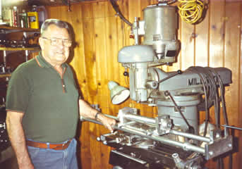
January 18, 2015 8:22 pmWe feel very fortunate to have recently obtained a twist deviation inspection machine developed by Mr. Manley Oakley of the Seattle, Washington area. This device checks the twist rate of a rifle barrel and determines if there is any deviation to the actual rate. Manley was the pioneer in this area of accuracy in rifle barrels. His inquisitive mind explored the consequences of twist deviation and he then engineered a machine to check rifle barrels for this condition.
Manley’s concept was actually quite simple. He theorized that if the twist rate of a rifle barrel was uniform for its entire length or if it had a slight gain in the actual twist rate, all other physical characteristics being as they should be, that barrel would be an accurate one. But if the twist rate varied, speeding up and then slowing down, or decreasing in rate towards the muzzle, that barrel would not be as accurate.
Manley verified his theory by checking barrels known to be accurate. He was a top benchrest shooter, having won several NBRSA National events and setting World’s records. And he was a top gunsmith, doing his own benchrest quality work. So Manley was able to judge a barrel’s performance on the target as well as anyone. He found that the best shooting barrels followed his theory and that other mediocre barrels did not show the twist uniformity that the accurate examples displayed.
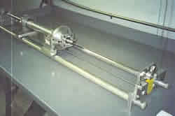
The question that Manley solved was; how do you check for twist deviation? He reasoned that if two plastic washers were spaced about 3 inches apart and pushed through a barrel, that the first washer would speed up or slow down in its rotation in relation to the trailing washer, if the twist rate changed. He devised a method of holding these washers on a long, small diameter steel tube. A smaller diameter rod fit inside of the tube and was free to rotate. The first washer was fixed to the small rod and the trailing washer to the tube. So now, if there was any change in twist rate, the inner rod would rotate faster or slower than the outer tube. With the rod running completely through the tube, the differences in rotation between the rod and tube could be observed and measured on the other end of the tube.
We borrowed this machine from Manley for several months in the late 1980’s to check our twist rates as we manufactured barrels. As a result of using it, we were able to fine tune our rifling process and deliver barrels with an optimum degree of twist rate uniformity.
Our barrels are buttoned rifled. The button is silver soldered to a “pull” rod and the rod is then attached to a guide. The guide has a helix milled in it with a lead angle equivalent to the nominal twist rate. For example, for a rifle barrel with a 10″ twist rate we select the pull guide with a helix that rotates once every 10 inches. A brass pin is inserted into the milled helical slot in the guide and it then rotates at the correct twist rate. A hydraulic cylinder pulls the guide.
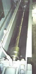
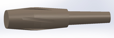
Here is a view of the helical rifling guide that controls the twist rate on the “pull” end of the button/rod. Near the top of the photo the brass pin can be seen that fits into the helical slot.
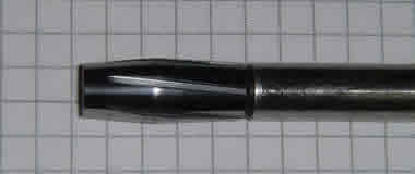
A button is a football shaped carbide tool that has grooves ground into it. The button is pulled through the barrel and the rifling grooves are formed into the barrel. The rifling lands remain in the barrel where the grooves in the button pass over them. But, these grooves ground into the carbide button must be ground on a true helix too and at the proper angle. Before a new button is made we calculate the correct lead angle for these grooves using a computer program developed by Dan. This angle depends on the diameter of the button and the twist rate we want.
So, we are able to accurately control the twist in our barrels as we rifle them through both the helix angle ground on the button and on the “pull” end of the rod with our helical guides.
Since we now have this twist machine in our shop on a permanent basis we can more closely monitor the twist of our barrels. Like our video borescope, this is one more tool we can use to help us deliver to you the best product we can manufacture.