Trigger Pin Drill Jig
January 23, 2015 2:35 amThis article was published in the May 1982 issue of Precision Shooting Magazine by then-editor Doc Garcelon. It was the first article I had published in a magazine. Though a little dated now, it describes the design and construction of a drill jig for locating trigger pin holes in a stock. When a Remington action is glued into a stock, either sleeved or as-is, it is necessary to provide access holes in the stock to allow removal of the trigger. I’ve included it in this action review section of our website in July of 2004 after I ran across it in an old file while looking for something else.
Gluing an action into a fiberglass stock is, I believe, the accepted method in building a competitive benchrest rifle. I don’t believe many will argue with that statement. Assembling a rifle in this manner is a relatively easy job to accomplish. There are a few considerations the stocker must make. Generally the standard bolt stop is replaced with an Allen head screw or a plunger type stop. This modification is made to simplify the glue-in process. Aside from port clearance, trigger guard relief, and bolt handle clearance which would be done in a conventional bedding job, he must provide sufficient room for the trigger to be removed through the bottom of the stock should it ever become necessary. In addition to the increased area around the trigger the stocker must provide access holes for the trigger pins so that they may be driven out. Drilling these holes appears easy but it can turn into a problem if your approximation of their location was wrong. It is not easy to get three holes in-line and much more difficult to do it twice.
There is a simple approach to this problem; well two ways really. One, let someone else do your stock work, or two (this is the method I like) build a simple drill jig. It may seem as though it would be much simpler to fill a dozen misplaced holes than machine a drill jig. It is not a difficult job however if you have access to a vertical mill. If the dimensions on the drawing and the instructions are followed the resulting jig should fit your Remington bolt action. With little or modification the jig should fit any action using a Remington-type trigger.
To begin machining the jig cut a piece of cold rolled 2” x 2” low carbon bar stock to a length of about 1.1” in the band saw. Take this block over to the milling machine. To keep everything square make sure the milling machine vise is parallel with the table travel with an indicator. Clamp the block in the vise with one of the saw cut edges protruding above the vise jaws and parallel to the quill. Clean up this face with an end mill leaving a smooth surface. Now that we have the this face perpendicular with the four surfaces as received from the steel mill, flip the block and repeat the operation on the other saw cut face. Mill this face leaving a thickness of 1.000”. After all this work we have a block that measures 1” x 2” x 2” with all the sides square. We are now ready to start by milling out the channel the full length of the block. Be careful in holding the .500”, 1.700”, and .750” dimensions shown on the drawing. Following this, turn the block on its rear side and cut the slot holding the 1.000” dimension shown in the top view of the drawing. With this same setup, the angle dimensioned .230” and 1.450” shown on the side view can be milled. Loosen the vise and set the jig on its “legs” and cut the .520” dimension. It should be mentioned that from now on that the block should be held with the “legs” perpendicular to the vise jaws as they could bend if tightened. Turn the block over again and zero off the back of the jig. In this operation the two radii on the .300” leg will be milled. The dimensions shown in the section view are to be held. The 45º angle dimensioned .275” and the 1.935” measurement can also be machined in this setup.

Remove the jig from the vise and it should now fit in the action. If not, check for burrs or where interference is occurring. When the jig fits easily we are ready to drill some holes. Place the jig in the vise on parallels with the legs facing you, the thicker one down. Using the edge finder, zero off the front and right side of the jig as it now sits. Place a #2 center drill in a collet. Traverse the table and center drill the positions dimensioned .230” and 1.425”. Remove the center drill and replace with a 1/8” diameter drill bit. Drill through both legs and we are about finished. With a little deburring we should have a finished and functional drill jig. After making sure it fit I painted mine with layout blue to prevent rust. If the jig is going to receive a good deal of use, hardened bushings could be easily installed or the entire jig could be carburized.
In practice the jig is placed in the action and the trigger pins driven through both. Prior to drilling the holes in the stock the action should be pre-bedded in the intended stock. This procedure eliminates and gross movement of the action in the stock, causing the holes to become out of alignment later. Place the jig and action assembly in the stock and slightly C-clamp them together. Run and 1/8” diameter drill bit through the jig and into the stock until the pins are met. Remove the jig from the action and reinstall the action in the stock. This time drill the hole completely through the action and through the other side of the stock. It is possible that the action with the trigger pins in place prior to drilling will not seat into the bedding because of a protruding end of a pin. If this is the case a knife blade can be used to remove the interfering portion of the bedding. The holes in the stock may now be opened up to 3/16” diameter. Be careful not to chip the fiberglass when doing this. I avoid that problem by using a high spindle speed and drill the holes from the outside only, not completely through. The original pins may be replaced with 1/8” diameter drill rod of a longer length making removal and insertion easier.
The time required making the jig is well spent when one considers the ease of obtaining perfectly aligned holes the first time and the professional appearance of the finished rifle.
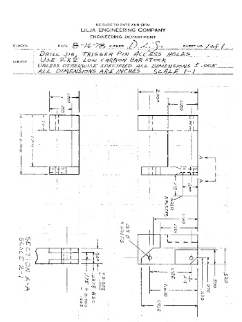
This is a scanned image of the original drawing from 1978. To see a full size version as a .pdf file drilljig1